Be yourself; Everyone else is already taken.
— Oscar Wilde.
This is the first post on my new blog. I’m just getting this new blog going, so stay tuned for more. Subscribe below to get notified when I post new updates.
Be yourself; Everyone else is already taken.
— Oscar Wilde.
This is the first post on my new blog. I’m just getting this new blog going, so stay tuned for more. Subscribe below to get notified when I post new updates.
2. The first project I found was a non-musical robotic hand, which the user could control. The hand would memorize the positions and be able to repeat the ways in which the user moved it by itself. https://create.arduino.cc/projecthub/ChanR19/simple-programmable-robotic-arm-bd28a0?ref=similar&ref_id=143911&offset=0
The second project I found was a Bluetooth Midi-Controlled Reed Organ that could take MIDI files and used a vacuum motor to work like a pump organ or player piano without the pumps. This was a big project, using three big Arduino chips, and the creator had to attach solenoids to each key on the keyboard. https://create.arduino.cc/projecthub/willem-hillier/bluetooth-midi-operated-antique-reed-organ-787495?ref=search&ref_id=music&offset=299
3. In digital electronics terms a switch or button is a analog input, an LED is an digital output, and a potentiometer is an analog input.
4. I took Intro to CS at NYU Fall 2019, where we worked in Java, but I admittedly did not enjoy it or do that great. Previously I’d taken a community college course in CS concepts Spring 2019.
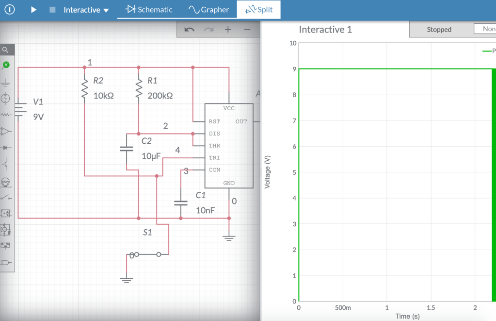
link to multisim site –
https://www.multisim.com/content/ovLz4q7mWrNNCASNSLRFuB/monostable-multivibrator/open
I found this project online that used a 555 timer chip in a monostable multivibrator to create a timed nightlight that would stay on for approximately 20 minutes.
It seems that larger companies often make the most basic forms of each effect, often creating the baseline, while smaller companies focus on more creative and specialized modulations of effects.
A pedal that seems unique is Fuzzrocious’ “Playing Mantis”, a drive pedal that also features a very strange synth-like oscillator that can double the signal. Even after reading so much about it, I feel that it is best understood by just watching this demo video:
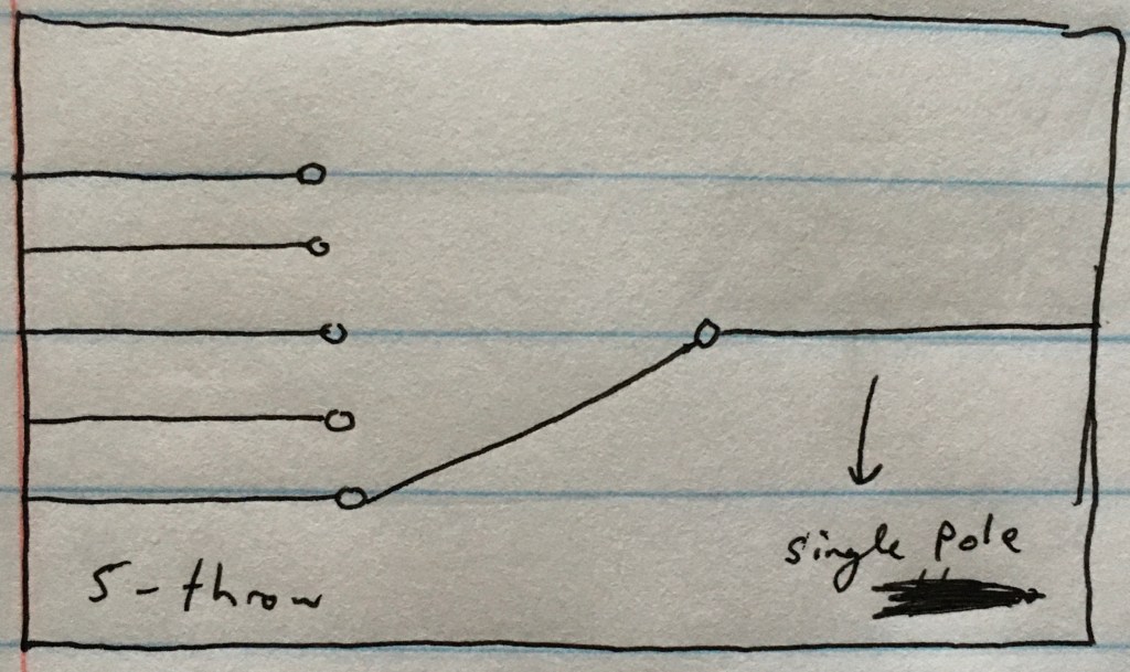
A momentary button sends a momentary signal and would pop back up again to allow for another immediately. A latching button holds down and sends a constant signal and would have to be manually turned off.
Link to circuit:
https://www.multisim.com/content/6N9SgHwJgjQvBedK96yAaK/week-10-lab/open
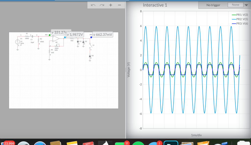
Adding a resistor and a capacitor to the inputs and outputs of the circuit is a good idea because the resistor can block any excessive AC current and the capacitor will block all DC current from going through the circuit.

The inverting amplifier, while also amplifying the signal, shifts the waveform 180 degrees. The noninverting amplifier does not.
video elements for this lab.
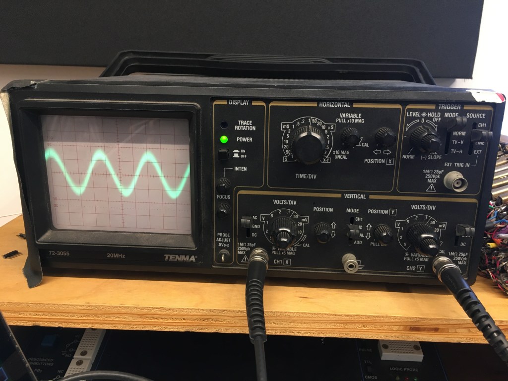
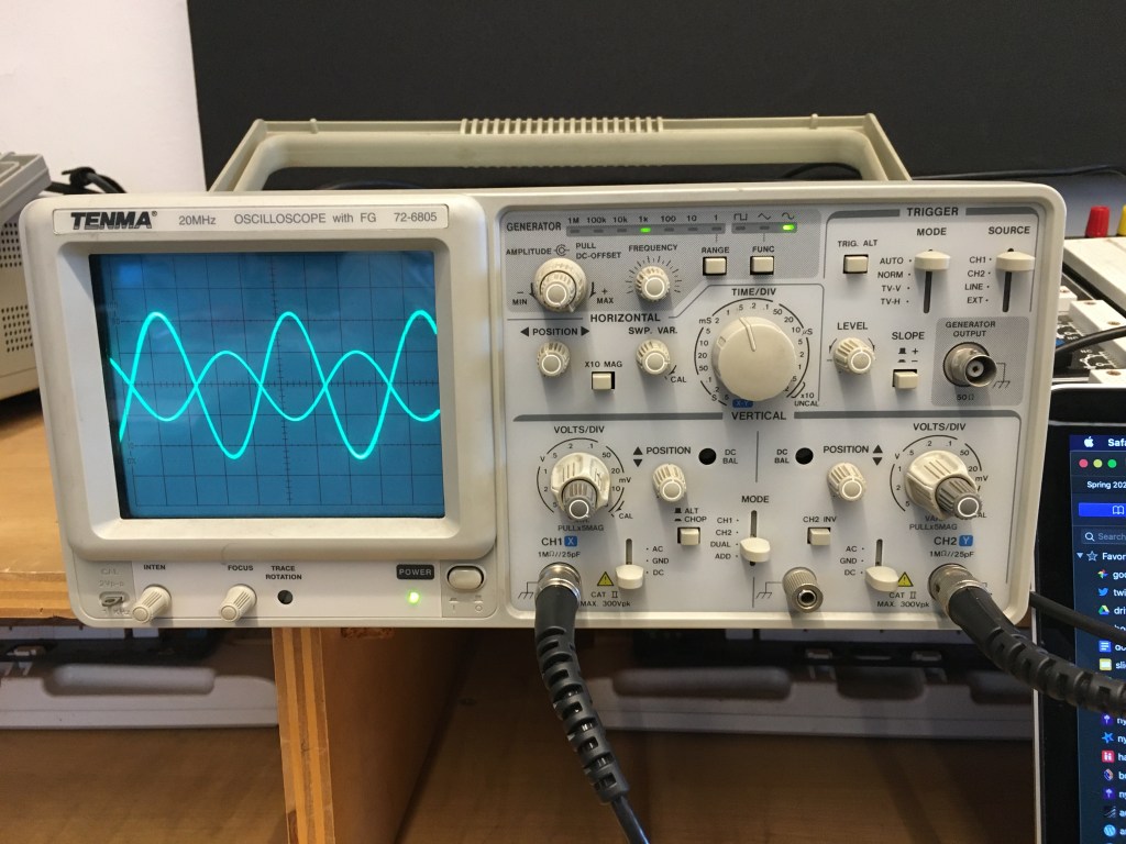
In the display section of the Oscilloscope, there is the power button, which turns the machine on or off, and the focus / intensity knobs, which control how thin / thick the wave is and how bright it is, respectively.
In the horizontal section, you can control the waveform’s horizontal center with the knob furthest right. The large knob is the the time/div knob, which changes the horizontal width of the waveform by affecting the amount of time represented by each mark on the graph.
Below is the vertical section. You can control the vertical height of the waveform with the volts/div knobs for each channel. You can also control the wave’s vertical center with the y-position knob and the type of current going through each probe, be it AC, DC, or ground.
The trigger controls on the top right-hand corner allow you to choose when the wave is displayed and which source is controlling that. The level-hold knobs are what allow you to focus on the wave in order to measure it.
The probes that stem from the vertical section each have two connectors that can be attached to two different points on the circuit. In. the video above, there are two different sine waves, and one’s amplitude is being affected by the potentiometer on the circuit. The potentiometer changes the resistance on the signal, going from about 1 Ω to 10 kΩ., with 1 Ω allowing 100% of the signal to come through and 10 kΩ not allowing anything at all.
1a. When you go to solder a component, you need to first wet your sponge, see if there’s any extra solder on the tip of the iron, and if so, wipe it off on the sponge. Then, turn on the iron and wait for the it to heat up and ensure its at about 750 degrees—usually the hottest setting. Then, test with the solder to see when it is hot, and then finally touch the iron to the component.
1b. Once you are done soldering, you need to wait a few seconds for the solder to cool and wipe off any extraneous solder onto the sponge. Then, place the iron back into the holster. After that, turn off the iron and make sure that the circuit is cool enough to touch before you pick it up.
2a. Before measuring current or voltage on the multimeter, you need to check that you are plugged into the right side, depending on which you want to measure. You also need to ensure that you are measuring DC power, rather than AC.
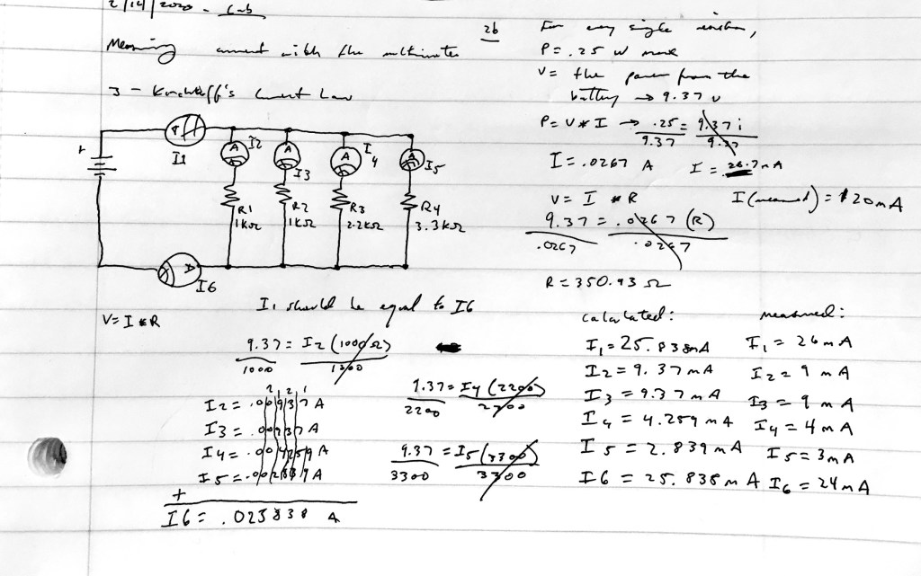
2b / 3